
In today's industrial landscape, selecting the right cable management solution for heavy-duty projects is crucial for operational efficiency and long-term reliability. Cable trays serve as the backbone of electrical infrastructure in manufacturing facilities, power plants, and large commercial buildings. These systems must withstand extreme conditions while providing secure pathways for critical electrical cables. Understanding which types offer the best performance characteristics can mean the difference between a successful installation and costly maintenance issues down the road.
Understanding Heavy-Duty Cable Tray Requirements
Load-Bearing Specifications and Standards
Heavy-duty applications demand cable trays that can support substantial weight loads while maintaining structural integrity over extended periods. Industrial facilities typically require systems capable of handling loads ranging from 50 to 200 pounds per linear foot, depending on the specific application. These specifications are governed by industry standards such as NEMA VE-1 and UL 568, which establish minimum performance criteria for cable tray systems. Engineers must carefully calculate the total weight of cables, including future expansion capacity, to ensure proper sizing and support spacing.
The load distribution characteristics of cable trays become particularly important in heavy-duty environments where cable runs may extend hundreds of feet without intermediate support. Proper load calculations must account for both static loads from the cables themselves and dynamic loads from thermal expansion, vibration, and potential seismic activity. Understanding these requirements helps facility managers select appropriate tray types and support structures that will perform reliably throughout their operational lifespan.
Environmental Resistance Factors
Heavy-duty installations often expose cable trays to harsh environmental conditions that can significantly impact their performance and longevity. Corrosive atmospheres, extreme temperatures, moisture exposure, and chemical contamination all present challenges that must be addressed through proper material selection and protective coatings. Stainless steel and aluminum alloys offer superior corrosion resistance compared to standard carbon steel options, making them ideal for chemical processing plants and marine environments.
Temperature cycling can cause significant thermal stress in cable tray systems, particularly in applications involving high-temperature processes or outdoor installations subject to seasonal variations. The coefficient of thermal expansion varies significantly between different materials, affecting joint design and support spacing requirements. Hot-dip galvanized steel trays provide excellent corrosion protection while maintaining cost-effectiveness for many industrial applications, though they may require additional considerations in extremely corrosive environments.
Ladder-Type Cable Tray Systems
Structural Advantages and Design Features
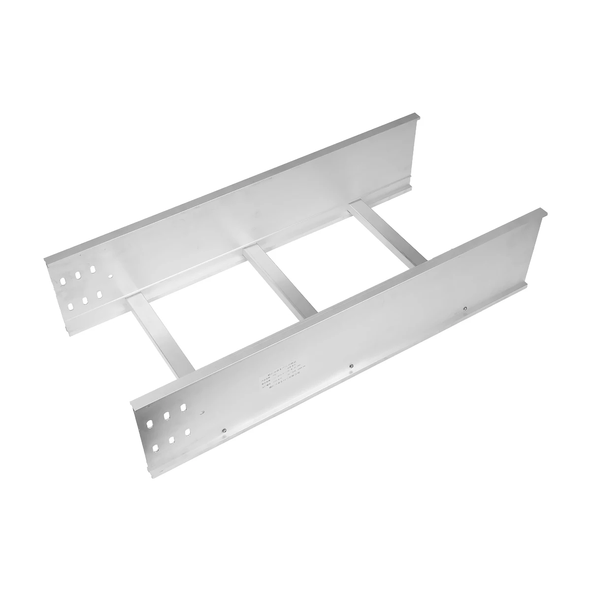
Ladder-type cable trays represent the most robust solution for heavy-duty applications, offering maximum load-bearing capacity and superior cable support characteristics. The continuous side rails and regularly spaced rungs create a rigid structure that distributes loads effectively across the entire span length. This design allows for longer unsupported spans compared to other tray types, reducing the number of support points required and simplifying installation in complex routing scenarios. The open construction facilitates excellent heat dissipation and allows for easy cable identification and maintenance access.
The rung spacing in ladder trays typically ranges from 6 to 24 inches, with closer spacing providing better support for smaller cables and reducing cable sag. Heavy-duty applications often utilize 12-inch rung spacing as an optimal balance between cable support and material efficiency. The side rail depth directly correlates to the tray's load-bearing capacity, with deeper rails providing greater structural strength for demanding applications. Premium cable trays feature reinforced connections and heavy-gauge materials to ensure reliable performance under maximum loading conditions.
Installation Flexibility and Customization Options
Ladder cable trays offer exceptional flexibility in routing configurations, accommodating complex three-dimensional pathways commonly found in industrial facilities. The modular design allows for easy field modifications and future expansions without requiring complete system replacement. Standard fittings include horizontal elbows, vertical bends, tees, and reducers that maintain the structural integrity of the system while providing smooth cable transitions. Custom fabrication options are readily available for unique routing requirements or specialized mounting conditions.
The compatibility with various cable types makes ladder trays particularly suitable for mixed-use installations where power, control, and communication cables must be routed together while maintaining proper separation distances. Dividers and barriers can be easily installed to create separate compartments within the same tray, optimizing space utilization while meeting electrical code requirements. This versatility reduces the total number of separate cable pathways required, simplifying installation and reducing overall project costs.
Solid Bottom Cable Tray Applications
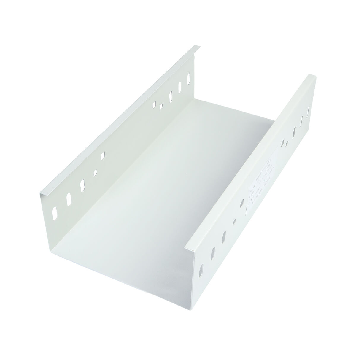
Enhanced Cable Protection Characteristics
Solid bottom cable trays provide maximum protection for sensitive cables in environments where contamination, debris, or liquid spillage poses significant risks. The continuous bottom surface creates a barrier that prevents foreign materials from falling onto cables while also containing any liquid that might accumulate within the tray system. This protection becomes critical in food processing facilities, chemical plants, and outdoor installations where environmental exposure could compromise cable integrity or create safety hazards.
The enclosed design also offers superior electromagnetic shielding properties, making solid bottom trays ideal for installations involving sensitive electronic equipment or high-frequency communication systems. The continuous metal enclosure helps reduce electromagnetic interference and provides a degree of physical security for critical control cables. However, this enhanced protection comes at the cost of increased weight and reduced heat dissipation compared to open tray designs, requiring careful consideration of thermal management in high-current applications.
Drainage and Maintenance Considerations
Proper drainage design becomes essential when implementing solid bottom cable trays in heavy-duty applications, particularly in outdoor or wash-down environments. Drain holes must be strategically positioned to prevent water accumulation while maintaining the tray's structural integrity. The sizing and spacing of drainage openings require careful calculation to ensure adequate water removal without compromising the protective characteristics of the solid bottom design.
Maintenance access considerations differ significantly from open tray systems, as the solid bottom construction limits visibility and accessibility to cables within the system. Regular inspection protocols must account for these limitations, potentially requiring removable covers or access panels at critical locations. The increased surface area of solid bottom trays also requires more comprehensive cleaning procedures in sanitary applications, impacting long-term maintenance costs and scheduling requirements.
Ventilated Cable Tray Solutions
Optimal Heat Dissipation Performance
Ventilated cable trays strike an optimal balance between cable protection and thermal management, making them particularly suitable for high-current applications in heavy-duty environments. The perforated bottom design allows for controlled airflow around cables while still providing substantial protection from debris and contamination. This design philosophy proves especially valuable in power distribution systems where cable ampacity limitations often determine the overall system capacity and efficiency.
The ventilation pattern and hole sizing directly impact both the thermal performance and structural characteristics of the tray system. Standard perforation patterns typically feature holes ranging from 0.5 to 1.5 inches in diameter, with total open area percentages between 25% and 40%. Higher open area percentages improve heat dissipation but may reduce structural strength, requiring careful engineering analysis to optimize performance for specific applications. The perforated design also provides some electromagnetic shielding benefits while maintaining superior thermal characteristics compared to solid bottom alternatives.
Structural Integrity and Load Distribution
The perforated bottom design of ventilated cable trays requires careful engineering to maintain adequate structural strength while maximizing thermal performance. The hole pattern and remaining material cross-section must be sufficient to support the calculated loads without excessive deflection or stress concentration. Advanced manufacturing techniques allow for optimized perforation patterns that maximize open area while maintaining structural integrity through strategic material distribution and reinforcement.
Load distribution characteristics in ventilated trays differ from both solid bottom and ladder designs, as the perforated bottom provides intermediate support for cables while allowing some degree of conformity to cable layouts. This flexibility can be advantageous in applications with varying cable sizes and configurations, as the tray adapts to the cable arrangement rather than forcing rigid geometric constraints. However, this adaptability requires careful consideration of cable support requirements and proper installation techniques to prevent damage during handling and installation.
Material Selection for Heavy-Duty Performance
Stainless Steel Advantages and Applications
Stainless steel cable trays represent the premium solution for the most demanding heavy-duty applications, offering unparalleled corrosion resistance and structural strength. The various grades of stainless steel provide different performance characteristics, with 316L offering superior chemical resistance for harsh industrial environments and 304 providing excellent general-purpose performance at lower cost. The inherent strength-to-weight ratio of stainless steel allows for longer spans and reduced support requirements compared to other materials, often offsetting the higher initial material costs through reduced installation complexity.
The non-magnetic properties of austenitic stainless steel grades make them particularly suitable for applications involving sensitive electronic equipment or precise instrumentation. The smooth surface finish resists particle accumulation and facilitates cleaning in sanitary applications, making stainless steel trays essential in pharmaceutical and food processing facilities. Long-term cost analysis often favors stainless steel in corrosive environments, as the virtually maintenance-free performance eliminates the recurring costs associated with protective coating renewal and system replacement.
Aluminum Alloy Performance Characteristics
Aluminum cable trays offer an attractive combination of lightweight construction, corrosion resistance, and cost-effectiveness for many heavy-duty applications. The natural oxide layer that forms on aluminum surfaces provides excellent protection against atmospheric corrosion, while the material's low density reduces both shipping costs and installation labor requirements. Aluminum's superior thermal conductivity enhances heat dissipation from cables, potentially allowing for higher current ratings in thermally limited applications.
The strength characteristics of aluminum alloys vary significantly depending on the specific alloy composition and temper designation, with 6061-T6 representing the most common choice for structural cable tray applications. While aluminum generally exhibits lower ultimate strength compared to steel, the reduced weight allows for optimized designs that achieve comparable performance with enhanced installation advantages. The material's compatibility with various protective coatings and anodizing treatments provides additional options for enhancing performance in specific environmental conditions.
Installation and Support System Design
Support Spacing and Structural Analysis
Proper support spacing represents a critical factor in heavy-duty cable tray installation, directly affecting both system performance and long-term reliability. The maximum allowable span between supports depends on multiple factors including tray type, material, loading conditions, and deflection criteria. Industry standards typically limit deflection to span/200 under full load conditions, though more stringent requirements may apply in applications involving sensitive equipment or precise cable routing requirements.
Structural analysis must consider both uniform loading from the distributed weight of cables and concentrated loads from cable pulling operations or maintenance access. Dynamic loading from thermal expansion, seismic activity, or equipment vibration requires additional consideration in critical applications. The support system design must also accommodate future cable additions and modifications without requiring major structural changes, necessitating conservative design approaches that account for potential load increases over the system's operational lifetime.
Seismic and Dynamic Load Considerations
Heavy-duty cable tray installations in seismically active regions require specialized design approaches that account for both lateral and vertical accelerations during seismic events. The lateral bracing system becomes particularly critical, as cable trays typically exhibit greater flexibility in the horizontal direction compared to vertical support structures. Proper seismic design ensures that the cable tray system can accommodate ground motion without imposing excessive forces on connected equipment or creating life safety hazards from falling components.
Dynamic loading considerations extend beyond seismic requirements to include vibration from rotating machinery, thermal cycling effects, and wind loading for outdoor installations. The natural frequency of the cable tray system must be sufficiently different from excitation frequencies to prevent resonance conditions that could lead to fatigue failure or excessive movement. Isolation techniques and damping systems may be necessary in applications where vibration control is critical for proper operation of sensitive equipment or prevention of cable fatigue.
FAQ
What load capacity should I expect from heavy-duty cable trays?
Heavy-duty cable trays typically support loads ranging from 50 to 200 pounds per linear foot, depending on the specific tray type, material, and support spacing. Ladder-type trays generally offer the highest load capacity, while the actual capacity depends on factors such as span length, material gauge, and safety factors required by local codes. Always consult with structural engineers and manufacturer specifications to determine appropriate load ratings for your specific application, as improper loading can lead to premature failure and safety hazards.
How do I choose between stainless steel and aluminum for harsh environments?
Stainless steel offers superior chemical resistance and strength for the most demanding applications, particularly in environments with acids, caustic solutions, or high chloride concentrations. Aluminum provides excellent atmospheric corrosion resistance and weight advantages but may not be suitable for certain chemical exposures or high-temperature applications. Consider factors such as specific chemical exposure, temperature ranges, structural requirements, and long-term maintenance costs when making material selections for harsh environment applications.
What spacing requirements apply to cable tray supports in heavy-duty installations?
Support spacing for heavy-duty cable trays typically ranges from 8 to 20 feet depending on the tray type, loading conditions, and deflection criteria. Ladder trays can generally accommodate longer spans compared to solid bottom or ventilated designs due to their superior structural characteristics. Local building codes and manufacturer specifications establish maximum allowable spans, but shorter spacing may be required to meet deflection limits or accommodate concentrated loads from cable pulling operations and maintenance access requirements.
Can different cable types be installed in the same heavy-duty tray system?
Multiple cable types can often be installed in the same tray system provided proper separation requirements are maintained according to electrical codes and standards. Power cables, control circuits, and communication cables typically require physical barriers or minimum separation distances to prevent interference and ensure safety. Dividers and barriers can be installed within cable trays to create separate compartments while optimizing space utilization and reducing the total number of separate pathways required for complex installations.