
 EN
EN
Installing insulating sleeves correctly is critical for ensuring electrical safety, preventing short circuits, and maximizing the operational lifespan of electrical components. Whether you are working with busbars, cable connections, or transformer terminals, proper installation techniques determine whether insulating sleeves will deliver the protection they are designed to provide. This comprehensive guide walks you through the essential steps, preparation requirements, and best practices for installing insulating sleeves to achieve maximum protection in industrial and commercial electrical systems.
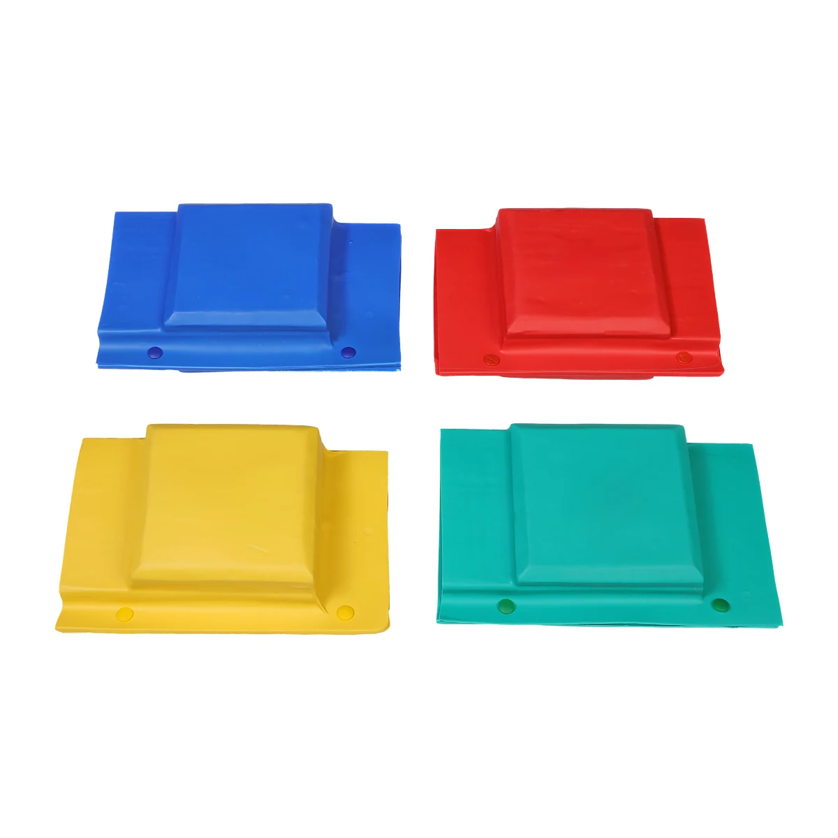
Understanding how to install insulating sleeves properly requires knowledge of material properties, sizing accuracy, heat application methods, and quality verification procedures. Many electrical failures attributed to insulation breakdown actually result from improper installation rather than material defects. This article provides detailed installation methodology that addresses surface preparation, positioning accuracy, shrinkage control, and post-installation inspection to help electrical professionals achieve reliable insulation performance consistently.
Understanding Installation Prerequisites and Component Selection
Accurate Measurement and Sleeve Sizing
Before beginning installation, precise measurement of the conductor or busbar diameter is essential for selecting appropriately sized insulating sleeves. The sleeve internal diameter before shrinkage should typically be twenty to thirty percent larger than the conductor diameter to allow easy positioning while ensuring adequate shrinkage ratio after heat application. Using calipers or measurement tapes designed for electrical components helps avoid sizing errors that compromise installation quality.
The length of insulating sleeves must account for overlap requirements at connection points and sufficient coverage beyond terminal areas. For busbar applications, sleeves should extend at least fifty millimeters beyond the connection hardware on each side to prevent exposure of conductive surfaces. When protecting cable splices, the sleeve length should cover the entire splice area plus additional margin to accommodate thermal expansion during operation.
Material selection impacts installation procedures significantly. Different insulating sleeves utilize polyolefin, polytetrafluoroethylene, silicone rubber, or other polymers with varying shrinkage ratios and temperature requirements. Verify that the selected sleeve material matches the operating temperature range, voltage rating, and environmental conditions of the application. Using insulating sleeves with appropriate specifications prevents premature degradation and maintains long-term protection.
Surface Preparation and Cleaning Requirements
Proper surface preparation directly affects adhesion quality and insulation performance of insulating sleeves. Begin by removing all oxidation, rust, grease, dust, and moisture from conductor surfaces using appropriate cleaning agents. For copper busbars, use lint-free cloths with isopropyl alcohol or specialized electrical contact cleaners. For aluminum conductors, ensure cleaning agents are compatible and do not promote further oxidation.
After chemical cleaning, mechanical surface preparation may be necessary for heavily oxidized components. Light abrasion with fine-grit sandpaper or wire brushes removes stubborn contaminants without damaging conductor surfaces. Follow mechanical cleaning with solvent wiping to eliminate any residual particles. Allow surfaces to dry completely before positioning insulating sleeves, as trapped moisture can create voids or bubbles during heat shrinking that compromise dielectric strength.
Inspect cleaned surfaces under adequate lighting to verify complete contaminant removal. Any remaining residue creates weak points in the insulation barrier where electrical tracking or moisture ingress can occur over time. For critical applications involving high voltage or harsh environments, consider using surface treatment compounds that enhance adhesion between insulating sleeves and conductor materials.
Tool Selection and Heat Source Preparation
Selecting appropriate heating tools determines installation quality and efficiency when working with heat-shrinkable insulating sleeves. Professional-grade heat guns with adjustable temperature controls provide precise heat application and prevent overheating that can damage sleeve materials. Set temperature ranges between one hundred twenty and two hundred degrees Celsius depending on the specific polymer composition of the insulating sleeves being installed.
For large-diameter busbars or extended installation projects, consider using industrial heat shrink ovens or infrared heating systems that deliver uniform temperature distribution. These tools reduce installation time while maintaining consistent shrinkage across the entire sleeve length. Portable propane torches can serve as alternative heat sources in field installations, but require careful technique to avoid concentrated heat spots that create uneven shrinkage or material degradation.
Supplementary tools including positioning guides, heat-resistant gloves, and temperature measurement devices improve installation accuracy and safety. Digital infrared thermometers allow real-time monitoring of surface temperatures during heat application, helping operators maintain optimal shrinking conditions. Keep fire suppression equipment readily accessible when working with open flame heat sources or in environments containing flammable materials.
Step-by-Step Installation Methodology
Positioning and Initial Placement
Slide the selected insulating sleeves onto conductors before making electrical connections when possible, as this simplifies positioning and eliminates the need for split-sleeve alternatives. For retrofit applications where connections already exist, use longitudinally slit insulating sleeves that can be wrapped around conductors and sealed during heat application. Ensure sleeves are centered over the area requiring protection with equal extension on both sides of connection points.
When protecting busbar connections, position insulating sleeves to cover bolt heads, washers, and any exposed metal that could create electrical hazards. Overlap adjacent sleeves by at least twenty-five millimeters at junction points to prevent gaps in the insulation barrier. For multi-conductor installations, stagger sleeve positions to avoid creating bulky areas where multiple overlaps coincide, which can complicate enclosure fitting and thermal management.
Mark the desired final position of insulating sleeves using heat-resistant tape or markers before beginning shrinkage. This reference prevents sleeve migration during heat application that could leave critical areas unprotected. For vertical installations, use temporary securing methods such as wire ties or clips to hold sleeves in position until initial shrinkage provides sufficient grip on conductor surfaces.
Heat Application Technique
Begin heat application at the center of insulating sleeves and work progressively toward both ends using smooth, sweeping motions. Maintain the heat gun nozzle at a distance of approximately ten to fifteen centimeters from the sleeve surface to distribute heat evenly without creating hot spots. Rotate conductors or move the heat source circumferentially to ensure uniform shrinkage around the entire diameter, preventing wrinkles or air pockets.
Monitor shrinkage progress visually as insulating sleeves transform from their expanded state to tight conformity with conductor contours. Properly installed sleeves should exhibit smooth surface finish without bubbles, wrinkles, or burnt areas. If adhesive-lined insulating sleeves are used, watch for adhesive flow at sleeve ends which indicates adequate heat penetration and proper sealing. Avoid excessive heating that can degrade polymer properties or cause dimensional distortion.
For large-diameter applications requiring extended heating time, work in sections to prevent adjacent areas from cooling before achieving complete shrinkage. Some specialized insulating sleeves incorporate color-changing indicators that signal when optimal installation temperature has been reached. These visual cues help operators achieve consistent results across multiple installations and reduce the risk of under-heating or over-heating.
Quality Verification During Installation
Conduct continuous quality checks throughout the installation process to identify and correct issues before they become permanent. Inspect shrinking insulating sleeves for uniform diameter reduction and absence of gaps between the sleeve and conductor surface. Gently probe the installed sleeve with a blunt tool to verify firm adhesion without detecting soft spots that indicate insufficient heat application.
For adhesive-lined insulating sleeves, verify that sealant has flowed beyond sleeve edges creating a visible bond line. This adhesive flow confirms moisture barrier integrity and mechanical retention. Check that no conductor surface remains exposed at sleeve terminations or overlap zones. Any visible metal requires additional sleeve coverage or extension before the installation can be considered complete.
Temperature verification using infrared thermometers during heat application ensures insulating sleeves receive adequate thermal input without exceeding material limits. Record installation parameters including heat gun settings, application duration, and ambient conditions for quality documentation. This data proves valuable for troubleshooting if insulation failures occur later and helps establish standard procedures for future installations.
Advanced Installation Considerations for Complex Applications
Multi-Layer Installation Techniques
High-voltage applications or severe environmental conditions may require multi-layer insulating sleeves for enhanced protection. When installing multiple layers, complete shrinkage of each layer fully before applying the next. This staged approach prevents air entrapment between layers that creates weak points in the composite insulation system. Allow adequate cooling time between layers to avoid cumulative heat buildup that can damage inner insulating sleeves.
Select outer layer insulating sleeves with slightly larger dimensions to accommodate the increased diameter created by inner layers. Stagger the termination points of different layers by at least fifty millimeters to eliminate continuous seams that could provide moisture ingress paths. For maximum protection, orient the longitudinal seam of outer layers opposite to inner layer seams in slit-sleeve installations.
Multi-layer systems benefit from using different material properties in each layer to optimize performance. An inner layer of soft, conformable insulating sleeves provides excellent surface contact and voltage withstand capability, while an outer layer of mechanically robust material protects against physical damage and environmental exposure. This complementary approach delivers superior overall protection compared to single-layer installations.
Special Considerations for Junction and Termination Points
Electrical junctions where multiple conductors converge require careful planning when installing insulating sleeves. Use molded or fabricated sleeve configurations designed specifically for T-joints, Y-connections, or multi-way branches rather than attempting to adapt straight sleeves. These specialized components provide complete insulation coverage without gaps while accommodating the geometric complexity of junction points.
At termination points where conductors connect to equipment terminals, ensure insulating sleeves extend close to the termination hardware without interfering with mechanical or electrical performance. Leave appropriate clearance for torque application during bolt tightening or connector assembly. Some installations benefit from flared-end insulating sleeves that transition smoothly from the protected conductor area to the termination point without creating stress concentration.
Cable entry points into enclosures or junction boxes present unique challenges for insulating sleeves installation. Coordinate sleeve dimensions with cable gland or seal specifications to ensure compatible fitment. Consider using stepped-diameter insulating sleeves that accommodate the diameter change between cable insulation and stripped conductor areas, providing continuous protection across the transition zone.
Environmental Adaptation Strategies
Installation environments significantly impact technique requirements and material selection for insulating sleeves. In high-humidity or outdoor locations, prioritize adhesive-lined sleeves that create moisture barriers and use supplementary sealants at termination points. Apply heat more gradually in cold environments where rapid temperature changes can cause condensation or thermal shock to brittle materials.
For installations in chemically aggressive environments, verify that insulating sleeves offer resistance to specific contaminants present. Perform compatibility testing if using cleaning agents or surface treatments not explicitly approved for the sleeve material. Some industrial settings require flame-retardant or self-extinguishing insulating sleeves that meet specific fire safety standards beyond basic electrical insulation requirements.
Vibration-prone installations benefit from mechanical retention features beyond heat-shrink grip alone. Consider installing locking cable ties or clamps at insulating sleeves terminations to prevent vibration-induced migration. In extreme temperature cycling environments, select sleeve materials with wide operating ranges and incorporate expansion accommodation in the installation design to prevent stress cracking during repeated thermal cycling.
Post-Installation Inspection and Quality Assurance
Visual Inspection Protocols
Comprehensive visual inspection after installation identifies defects requiring correction before energizing electrical systems. Examine the entire length of installed insulating sleeves under proper lighting conditions, looking for surface irregularities including wrinkles, bubbles, burns, cracks, or incomplete shrinkage. Any of these conditions indicates installation problems that compromise protective performance and require sleeve replacement or correction.
Verify that insulating sleeves exhibit uniform color throughout their length without discoloration patterns suggesting overheating. Check termination points carefully to confirm no conductor exposure exists and that overlap zones show proper bonding. For adhesive-lined sleeves, confirm visible adhesive flow at both ends indicating complete environmental sealing has been achieved.
Inspect the installation site for proper clearance between insulated conductors and surrounding structures, ensuring adequate spacing for voltage rating and thermal dissipation. Document installation quality through photography, particularly for critical circuits or locations that will become inaccessible after equipment assembly. These records provide valuable reference for maintenance activities and failure investigation if issues arise during operation.
Electrical Testing Procedures
Electrical testing validates that installed insulating sleeves meet required performance standards before system commissioning. Perform insulation resistance testing using a megohmmeter at voltage levels appropriate for the circuit rating. Measure resistance between insulated conductors and ground, as well as between adjacent insulated conductors, to verify adequate dielectric strength. Minimum acceptable values depend on voltage class but typically range from hundreds of megohms to several gigohms for properly installed insulating sleeves.
For high-voltage applications, conduct dielectric withstand testing at voltages exceeding normal operating levels to verify installation integrity. Apply test voltage gradually while monitoring for sudden resistance drops or current surges indicating insulation weakness. Follow applicable safety standards and use appropriate personal protective equipment during high-voltage testing procedures.
Thermal imaging inspection after initial energization identifies hot spots suggesting poor contact, excessive resistance, or inadequate insulation. Compare temperature readings of insulated connections against similar uninsulated reference points or manufacturer specifications. Elevated temperatures may indicate installation defects requiring investigation and correction despite passing initial electrical tests.
Documentation and Maintenance Planning
Complete installation documentation establishes baseline conditions for future maintenance and troubleshooting activities. Record details including insulating sleeves specifications, installation date, personnel involved, environmental conditions, and test results. Photograph installations from multiple angles showing sleeve positioning, overlap details, and relationship to surrounding components.
Develop maintenance schedules based on environmental exposure and criticality of protected circuits. Periodic inspection of insulating sleeves should examine surface condition, checking for cracking, discoloration, mechanical damage, or signs of tracking. Environmental monitoring for temperature extremes, moisture ingress, or chemical exposure helps predict when sleeve replacement may become necessary before failure occurs.
Establish replacement criteria specifying conditions requiring immediate sleeve renewal versus those allowing continued operation with increased monitoring. Include installation records in equipment maintenance files and electrical drawings to assist future technicians who may need to modify or repair protected circuits. Proper documentation ensures installation knowledge transfers effectively across personnel changes and time.
Troubleshooting Common Installation Problems
Addressing Incomplete Shrinkage Issues
Incomplete shrinkage of insulating sleeves results from insufficient heat application, incorrect material selection, or expired shelf-life products. When sleeves fail to conform tightly to conductor surfaces, gaps allow moisture ingress and reduce dielectric strength. To correct this problem, apply additional heat using careful technique to avoid overheating previously shrunk areas. Use lower heat gun settings and longer application duration rather than high temperatures that risk material damage.
If additional heating fails to achieve proper shrinkage, the insulating sleeves may be incompatible with the application or have exceeded storage life. Cross-linked polymers used in heat-shrinkable products have limited shelf life after which shrinkage properties degrade. Replace suspect sleeves with fresh material from verified inventory, ensuring proper storage conditions prevent premature aging of replacement stock.
Ambient temperature significantly affects shrinkage behavior of insulating sleeves. In cold environments below ten degrees Celsius, materials become less pliable and require higher heat input or pre-warming before installation. Use heating blankets or enclosures to raise ambient temperature around the installation area when working in cold conditions. Conversely, extremely hot environments may cause premature shrinkage during positioning, requiring faster working techniques or climate control.
Correcting Surface Defects and Damage
Surface bubbles or blisters in installed insulating sleeves indicate trapped air or moisture, contaminated conductor surfaces, or excessive heating. Small bubbles may not immediately compromise insulation performance but create stress concentration points where cracking can initiate. For critical applications, remove defective sleeves and repeat installation after verifying surface cleanliness and using proper heat application technique.
Wrinkles or folds in insulating sleeves result from uneven heat application or sleeve material gathering during shrinkage. While minor wrinkles may be cosmetically acceptable, significant folds reduce effective insulation thickness and create tracking paths. Prevent wrinkles by maintaining continuous heat application while manually smoothing the sleeve surface using heat-resistant gloves. For severe wrinkling, sleeve replacement provides more reliable protection than attempting to remove wrinkles from installed sleeves.
Mechanical damage to insulating sleeves during or after installation requires immediate attention. Cuts, abrasions, or punctures expose conductor surfaces and eliminate insulation protection. Apply repair sleeves over damaged areas, ensuring adequate overlap with undamaged material on both sides of the defect. For extensive damage, complete sleeve replacement may be more reliable than multiple repair patches that create potential weak points.
Managing Dimensional and Fit Problems
Oversized insulating sleeves that remain loose after full shrinkage fail to provide adequate insulation or environmental protection. This problem results from incorrect size selection or using sleeves with insufficient shrink ratios for the application. Verify the shrink ratio specification of installed sleeves matches the dimensional difference between conductor and pre-shrink sleeve diameter. Replace improperly sized sleeves with correctly specified products rather than attempting to compensate with additional layers or mechanical securing methods.
Undersized insulating sleeves create installation difficulty and may tear during application. Attempting to force small sleeves onto large conductors typically results in material failure or incomplete coverage. When size errors are discovered during installation, stop immediately and obtain correct sleeves rather than compromising installation quality. Maintain organized inventory with clear size labeling to prevent selection errors in future installations.
Length inadequacy becomes apparent when insulating sleeves fail to provide required coverage after installation. This problem necessitates sleeve removal and replacement with longer products, as attempting to patch gaps with additional short sleeves creates reliability concerns. Calculate required lengths carefully before beginning installation, accounting for overlap requirements, terminal coverage, and potential sleeve migration during heat application.
FAQ
What is the minimum overlap distance required when joining two insulating sleeves on the same conductor?
The minimum overlap distance between adjacent insulating sleeves should be at least twenty-five millimeters to ensure continuous insulation coverage without gaps. For high-voltage applications or harsh environments, increase overlap to fifty millimeters or more. The overlap zone should receive thorough heat application to bond both sleeves together, creating an integrated insulation barrier. Consider using adhesive-lined insulating sleeves at overlap points to enhance moisture sealing and mechanical retention in critical installations.
Can insulating sleeves be removed and reinstalled if adjustments are needed after shrinking?
Once heat-shrinkable insulating sleeves have been fully installed, they cannot be removed and reused because the shrinking process permanently alters the molecular structure of the polymer material. Attempting to heat and expand shrunk sleeves typically results in material degradation, dimensional instability, and compromised insulation properties. If repositioning becomes necessary after installation, cut away the existing sleeve completely and install a new replacement sleeve following proper procedures. This approach ensures reliable insulation performance rather than risking failure from reused materials.
How do you install insulating sleeves on energized conductors safely?
Installing insulating sleeves on energized conductors presents serious safety hazards and should only be performed by qualified personnel using appropriate hot work procedures and personal protective equipment rated for the voltage level involved. Use split-sleeve designs specifically manufactured for energized installation that can be wrapped around conductors without requiring disconnection. Follow lockout-tagout procedures whenever possible to de-energize circuits before sleeve installation. If energized work is unavoidable, employ insulated tools, maintain proper approach distances, and ensure continuous supervision by qualified safety personnel throughout the installation process.
What causes insulating sleeves to crack or become brittle after installation?
Cracking or brittleness in installed insulating sleeves results from several factors including ultraviolet radiation exposure, extreme temperature cycling, chemical contamination, or material aging beyond design life. Outdoor installations require UV-resistant sleeve formulations that incorporate stabilizers preventing photodegradation. Operating temperatures exceeding material specifications accelerate aging through thermal stress and polymer breakdown. Chemical exposure from industrial atmospheres or cleaning agents can attack sleeve materials causing surface degradation. Regular inspection identifies early signs of deterioration allowing preventive replacement before insulation failure occurs. Proper material selection matching environmental conditions significantly extends sleeve service life.
Table of Contents
- Understanding Installation Prerequisites and Component Selection
- Step-by-Step Installation Methodology
- Advanced Installation Considerations for Complex Applications
- Post-Installation Inspection and Quality Assurance
- Troubleshooting Common Installation Problems
-
FAQ
- What is the minimum overlap distance required when joining two insulating sleeves on the same conductor?
- Can insulating sleeves be removed and reinstalled if adjustments are needed after shrinking?
- How do you install insulating sleeves on energized conductors safely?
- What causes insulating sleeves to crack or become brittle after installation?